• +39 02 26826332
  • This email address is being protected from spambots. You need JavaScript enabled to view it.

Tank mixing systems

Liquid jet mixing nozzles and tank mixing systems

 Tank mixing systems

Ourliquid jet mixing nozzles are the main components of special mixing systems which can be applied for continuous as well as discontinuous mixing duties. 

They can be used as complete replacement for mechanical agitators and in many cases they surpass their mixing results.

Working principle

A liquid flow is taken from the tank and supplied to the liquid jet mixing nozzles via a motive pump. Inside the motive nozzle pressure energy is converted into kinetic energy. Negative pressure is generated at the motive nozzle outlet and the ambient liquid is sucked in. The suction flow is strongly intermixed with the motive flow in the adjoining mixing section and accelerated by impulse exchange. The drag effect of the exiting mixed flow increases the mixing effect.

Advantages of the mixing nozzles

1
Complete mixing of the tank content
2
Low investment costs
3
Wear-resistant, long service life - no moving parts inside the tank
4
No sealing problems - no shaft ducts
5
No dead zones
6
No maintenance in the tank
7
Low energy input
Mixing nozzles are customised designed for every application

Fields of application

1
Mixing storage tanks, fuel oil tanks, waste water treatment tanks, neutralisation tanks, reactors, food storage tanks, storm water tanks and others
1
Complete homogenisation of different liquids
1
Preventing settlements and sedimentation
1
Avoiding the formation of different temperature layers
1
As discharge support
1
For waste water treatment applications (ejectors in SBR-Plants operated with compressed air)
Working principle of a Körting mixing nozzles
Operation, application prerequisites and limitations
Mixing nozzles consist of a motive nozzle and a mixing section. The liquid motive medium introduced under pressure via the motive connection is usually taken from the tank and delivered into the liquid jet mixing nozzle by means of a mechanical pump mounted outside of the tank. In the motive nozzle the static pressure of the motive medium is converted into velocity generating a corresponding negative pressure at the suction openings which is utilised to draw in the so-called suction flow.

Suction and motive flow are intermixed intensively in this turbulent region at the motive nozzle outlet as well as in the adjoining mixing section and are subsequently supplied into the tank as mixed flow. The volume ratio between suction and motive flow is about 3:1. The mixed flow exits the mixing nozzle with relatively high velocity and encounters the liquid contained in the tank, which is subsequently entrained as a result of the mixed flow’s drag effect, so that finally the sum of motive flow, suction flow and drag flow keeps the liquid inside the tank moving.

Application prerequisites and limitations
Motive flow and suction flow are mixed in the mixing section behi nd the motive nozzle, so that a homogeneously mixed liquid jet develops in the mixing section due to high tur bulence resulting from motive and suction flow.

In case of liquids with physical properties like water, a mixin g ratio of motive flow to suction flow is 1:3. On account of its velocity and of the dragging jet effect resultin g therefrom, the mixed flow leaving the liquid jet mixing nozzle carries forward so much surrounding liquid that t he used motive flow is multiplied. In case of liquids with higher viscosity the mixing ratio and the dragging effect are decreased.

The limiting range for applying liquid jet mixing nozzles is reached when the viscosity of the liquid to be circulated does not allow a delivery with centrifugal pumps anymore. The m otive flow passed through the liquid mixing nozzles of a certain size depends on the efficient motive pressu re. If the motive liquid is removed from the mixing tank this efficient motive pressure is to be equated with the de livery head of the centrifugal pump after deduction of all pipe friction losses.

In case where the motive liquid is not to be removed from the mixing tank the liquid column above the liquid jet mixing nozzle outlet is to be taken into account for determinin g the efficient motive pressure.
Structure and function of tank mixing systems
Properties of a tank mixing system for edible oil
CFD basics

When using the Computational Fluid Dynamics (CFD) model for mixing systems some helpful simplifications are used:

  • steady state modelling (not transient)
  • turbulent flow modelled with of two equation turbulence model
  • numerical grid with tetrahedral cells
  • smooth liquid surface
  • modelling of pipings and support plates, if required
  • physical properties of the flow medium, e.g. fuel oil with high dynamic viscosity (up to 500 mPas)
Installiertes Mischsystem in einem Tank für Speiseöl

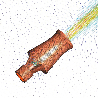
Numerical set-up for a storage tank 
(D = 68 m; H = 23 m)

mixing nozzles: 60 x 2“
tank volume: 80000 m³

  • generating a CAD file
  • creating a numerical grid
  • solving the conservation equations
  • post process results

Numerical flow simulation

The aim of the numerical tests carried out is an optimum arrangement of the mixing nozzles inside the tank with regard to the a.m. design strategy. The tests are based on a liquid-filled cylindrical tank.

Various combinations of flow medium and tank geometry can be optimised for customer specific tests per CFD by selecting corresponding physical material characteristics of the flow medium resp. special geometry requirements. The tank geometry to be tested is simulated by means of a CAD program. Digital geometry information of the individual mixing nozzles is imported directly from CAD systems used in the design process. Number, position and alignment of the simulated mixing nozzles inside the tank are determined, so that the complete tank configuration can be simulated digitally.

The whole simulated geometry consisting of all liquid jet mixing nozzles and the tank with pump connection is converted to a calculation grid by means of a so-called grid generator which is the basis of the CFD. The fluidic fundamental equations are solved for each of the cells generated within the grid.

Primarily, these are the conservation equations for mass, impulse and energy. Two further conservation equations will be solved in order to consider the turbulence caused by the liquids. All conservation equations are solved by means of the so-called equation resolver. In order to simplify the calculations they are based on stationary flow conditions. The whole simulation process from the grid generation up to the representation of the results takes place automatically for the most part.

On the one hand, geometrical boundary conditions for the simulation are the tank dimensions (filling height H, tank diameter D) as well as the position and size of the pump connections and on the other hand the number, position and alignment of the liquid jet mixing nozzles. Operational boundary conditions are determined by the motive pressure at the liquid jet mixing nozzle and the physical properties of the motive flow.


Examples of CFD calculation results

Edible oil tank


H=30 m; D=19 m

CFD Simulation Speiseöltank 
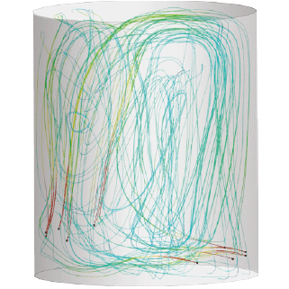
mixing nozzles: 32 x 2 Zoll
tank volume: 8500 m³
motive flow rate: 790 m³/h
liquid density: 910 kg/m³
liquid viscosity: 35 mPas
mixing power: 5.2 W/m³
average liquid velocity: 0.17 m/s

Waste water tank


H=14.6 m; D=42 m

CFD Simulation Abwassertank 
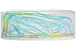
mixing nozzles: 25 x 2 Zoll
tank volume: 20200 m³
motive flow rate: 770 m³/h
liquid density: 900 kg/m³
liquid viscosity: 50 cpoise
mixing power: 4.2 W/m³
average liquid velocity: 0.09 m/s

Fuel oil tank


H=16 m; D=2.9 m, 
Filling height=2.6 m

CFD Simulation Treibstofftank tank volume: 60 m³
motive flow rate: 12.8 m³/h
mixing power: 320 W/m³
average liquid velocity: 0.24 m/s


Computational Fluid Dynamics (CFD)

To determine the optimum configuration of our tank mixing systems we perform Computational Fluid Dynamics (CFDbased on the current specific frame conditions. These analyses enable us to define the exact performance data as well as the best possible installation position to avoid any dead zones inside the tank. By using Computational Fluid Dynamics (CFD) we are able to deliver perfect designed tank mixing system, to decrease the energy input and to deliver clear installation instructions which enable a quick startup of the system.

IMAGE: Example of a Computational Fluid Dynamics (CFD) for an edible oil tank - optimum application without dead zones
Example of a Computational Fluid Dynamics (CFD)

We are using cookies to give you the best experience on our site. By continuing to browse the site you are agreeing to our use of cookies.